Developer Manual/Tools/Dual Flash: Difference between revisions
Jump to navigation
Jump to search
(Created page with "== Dual Parallel Flash == [[File:Dual_parallel_flash.jpg|400px|thumb|left|Dual flash "pie". One for keeping working firmware image. Flash chips are selectable by a tumbler switc...") |
|||
| Line 1: | Line 1: | ||
== Dual Parallel Flash == | == Dual Parallel Flash == | ||
You may do it yourself. That's a great tool getting away from bricks :) | |||
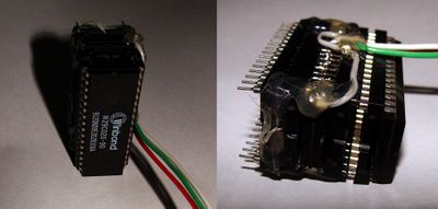
[[File:Dual_parallel_flash.jpg|400px|thumb|left|Dual flash "pie". One for keeping working firmware image. Flash chips are selectable by a tumbler switch]] | [[File:Dual_parallel_flash.jpg|400px|thumb|left|Dual flash "pie". One for keeping working firmware image. Flash chips are selectable by a tumbler switch]] | ||
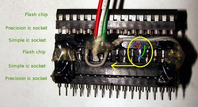
[[File:Pie2.jpg|400px|thumb|left|Detailed "pie" structure. In a yellow ellipse you can see blue lines, that shows how to bend pins]] | [[File:Pie2.jpg|400px|thumb|left|Detailed "pie" structure. In a yellow ellipse you can see blue lines, that shows how to bend pins]] | ||
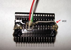
[[File:Pie1.jpg|300px|thumb|left|VCC is connected to pull-up resistors]] | [[File:Pie1.jpg|300px|thumb|left|VCC is connected to pull-up resistors]] | ||
[[File:Pull-ups.jpg|300px|thumb|left|Resistors are about 100 k?. Please note that green and red wires are also connected to their corresponding flash chip's chip select signal]] | [[File:Pull-ups.jpg|300px|thumb|left|Resistors are about 100 k?. Please note that green and red wires are also connected to their corresponding flash chip's chip select signal]] | ||
Revision as of 22:10, 18 May 2011
Dual Parallel Flash
You may do it yourself. That's a great tool getting away from bricks :)


