DIY EHCI debug dongle
The wiki is being retired!
Documentation is now handled by the same processes we use for code: Add something to the Documentation/ directory in the coreboot repo, and it will be rendered to https://doc.coreboot.org/. Contributions welcome!
Hardware
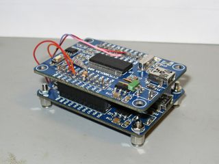
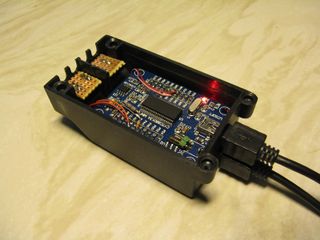
A dongle to debug target with EHCI Debug Port capability can be built using two Cypress CY7C68013A (aka FX2LP) USB device chips. Theory of operation is described in Cypress Application Note AN63787[1].
There are a few boards in the 10-15 EUR pricerange to choose from and a dozen suppliers in ebay.
A slower uni-directional boot console has been demonstrated to work with one FX2LP and a TTL-UART-to-USB adapter. In theory at least, some JTAG dongles with FX2LP could be used to capture coreboot console from EHCI debug port.
Prototype
LCSoft FX2LP
Schematics for prototype board and required modification.
There are at least two different versions of this board. The old version with only one LED (just connected to the supply), capacitors on the bottom side of the PCB and the reset taster near the EEPROM is the one used in the prototype shown above. The new version doesn't have capacitors on the bottom side of the PCB, the reset taster near the USB port and three LEDs. The two additional LEDs are connected to PA0 and PA1, which I removed. There is also a 10k resistor connected to the A0 pin of the EEPROM, so you just have to remove the jumpers. The resistor on the reset pin is not R2 but R3. RDY0 und RDY1 are swapped on the silkscreen, but the pins are connected to the same pins of the FX2LP as on the old version, so that's just an error in the silkscreen.
Warning: On J2 the supply pins 10 and 19 are swapped (one is GND and one is VCC), so you also have to remove these two pins from the J2-F connector if you use one new and one old version of the PCB for this project.
Firmware
Firmware is built with sdcc using fx2lib.
Original git repository [2]. Offline.
Recent updates are here [3].
More recent code is available at [4]. Note that it uses different pin assignments than the code in the previous repository.
You have to flash the same debugdevice_full_duplex firmware on both boards.

